
Polarity Basics
What is Polarity in Fiber Optic Networks?
Polarity in fiber optic networks refers to the alignment of transmit (Tx) and receive (Rx) signals between interconnected devices. In fiber optics, data travels from the Tx port of one device to the Rx port of another, forming a two-way communication path. For this signal alignment to work properly, the fiber cables and connectors must be arranged so that each Tx connects to the correct Rx.
Why Polarity Matters?
Signal Integrity: Correct polarity ensures signals are received at the correct port, preventing data transmission errors and ensuring network efficiency.
High-Speed Connectivity: In multi-fiber systems, such as those using MTP®/MPO connectors, polarity management is critical to maintain proper Tx/Rx orientation across multiple fibers simultaneously, especially in high-density and high-speed applications (e.g., 40G, 100G, 400G).
Methods of Managing Polarity
Polarity is managed through various cabling standards and methods (Types A, B, and C), which control how fibers are aligned in multi-fiber connections. This ensures consistent Tx/Rx matching across all connections, making it possible for complex network systems to operate without interruptions.
Correct polarity is essential for efficient, high-performance fiber optic networks, especially in data centers and enterprise networks that rely on high-density, parallel connections. This article describes the following three key concepts of polarity in fiber optic networks. Together, these concepts enable reliable, high-performance communication in modern fiber optic networks.
Key Concepts:
01 LC/SC Duplex Polarity
Duplex Connectors: LC and SC connectors have two fibers—one for transmit (Tx) and one for receive (Rx).
A-B (Crossover) Polarity: Standard configuration, where Tx on one end connects to Rx on the other.
A-A (Straight Through) Polarity: Less common configuration where Tx connects to Tx and Rx connects to Rx on both ends.
Maintaining Polarity: Using A-B LC duplex patch cords ensures proper Tx/Rx alignment in duplex connections.
02 MTP®/MPO Polarity
(Base-8) and (Base-12) Connectors: MTP®/MPO connectors in Base-8 and Base-12 systems contain either 8 or 12 fibers, respectively, for high-density parallel transmission. Base-8 is optimized for 40G and 100G applications, while Base-12 is commonly used in 40G, 100G, and 400G networks.
Polarity and Connection Types: Polarity methods (Type A, B, or C) are used in both Base-8 and Base-12 systems to ensure correct Tx/Rx alignment across all fibers, minimizing connection errors.
Polarization Methods (Type-A/B/C): Three Polarization Methods of MTP®/MPO Trunk Cable Type A (Straight-Through), Type B (Reversed) and Type C (Pair Flipped)
03 MTP®/MPO Polarity Management Methods
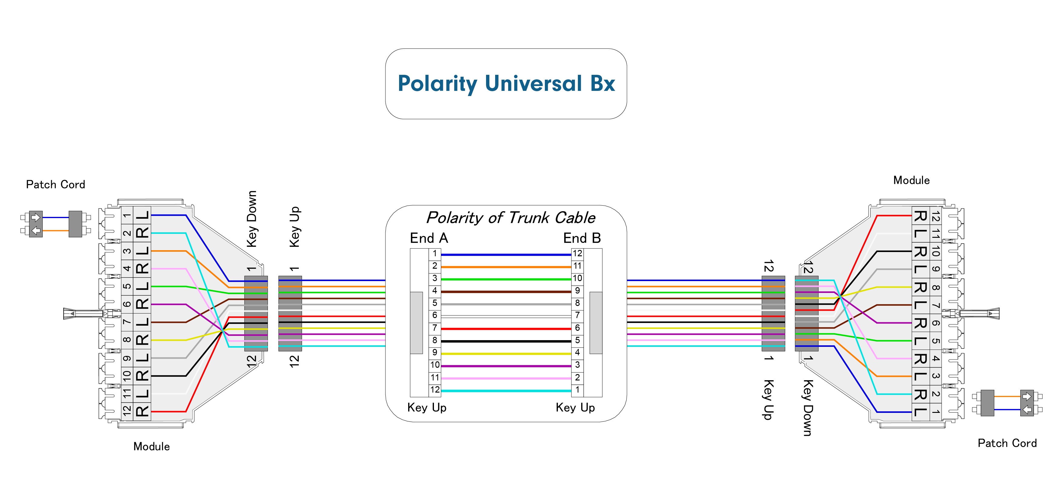
The proper MTP®/MPO polarity management methods are defined here in this article by TIA/EIA 568 standard as Method A, Method B, Method C and Universal System. Scroll down to read complete guide.
These methods ensure consistent, accurate polarity in high-density networks, optimizing transmission quality across various fiber optic setups. When setting up distribution areas or cross-connects, it’s essential to use standardized patch cables (such as A-B LC duplex patch cords) to maintain polarity and prevent Tx-Rx misalignment. Following these practices ensures seamless data transmission and efficient operation in high-speed network environments.
LC/SC Duplex Polarity
In fiber optic networks, LC and SC duplex connectors are widely used for reliable data transmission, each featuring two fibers—one designated for transmit (Tx) and the other for receive (Rx). Duplex connections are essential for two-way communication, as each device requires both sending and receiving capabilities for effective data flow.
Polarity in this context refers to the correct alignment of the Tx and Rx fibers between interconnected devices. Ensuring proper polarity means that the Tx port of one device connects directly to the Rx port of the other device and vice versa. This alignment is crucial to avoid signal errors, reduce downtime, and maintain high-speed, efficient network performance.
Polarity Types for LC/SC Duplex Connectors:
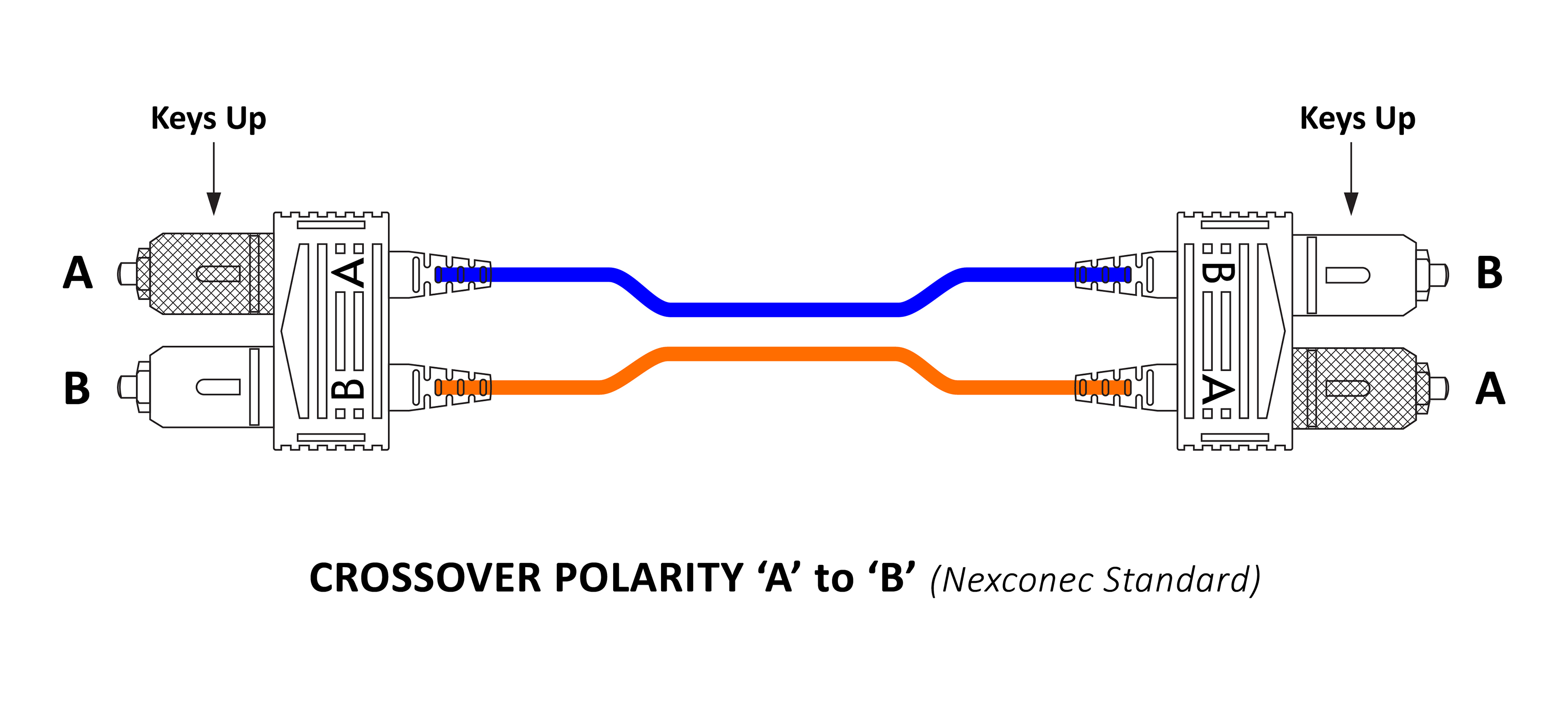
01 A-B (Crossover) Polarity
This is the standard polarity configuration for duplex connections. In (A-B) polarity, the transmit signal on one end (fiber A) aligns with the receive signal on the opposite end (fiber B). This straight-through connection allows data to flow seamlessly between devices, and A-B polarity is generally achieved with standard A-B duplex patch cords.
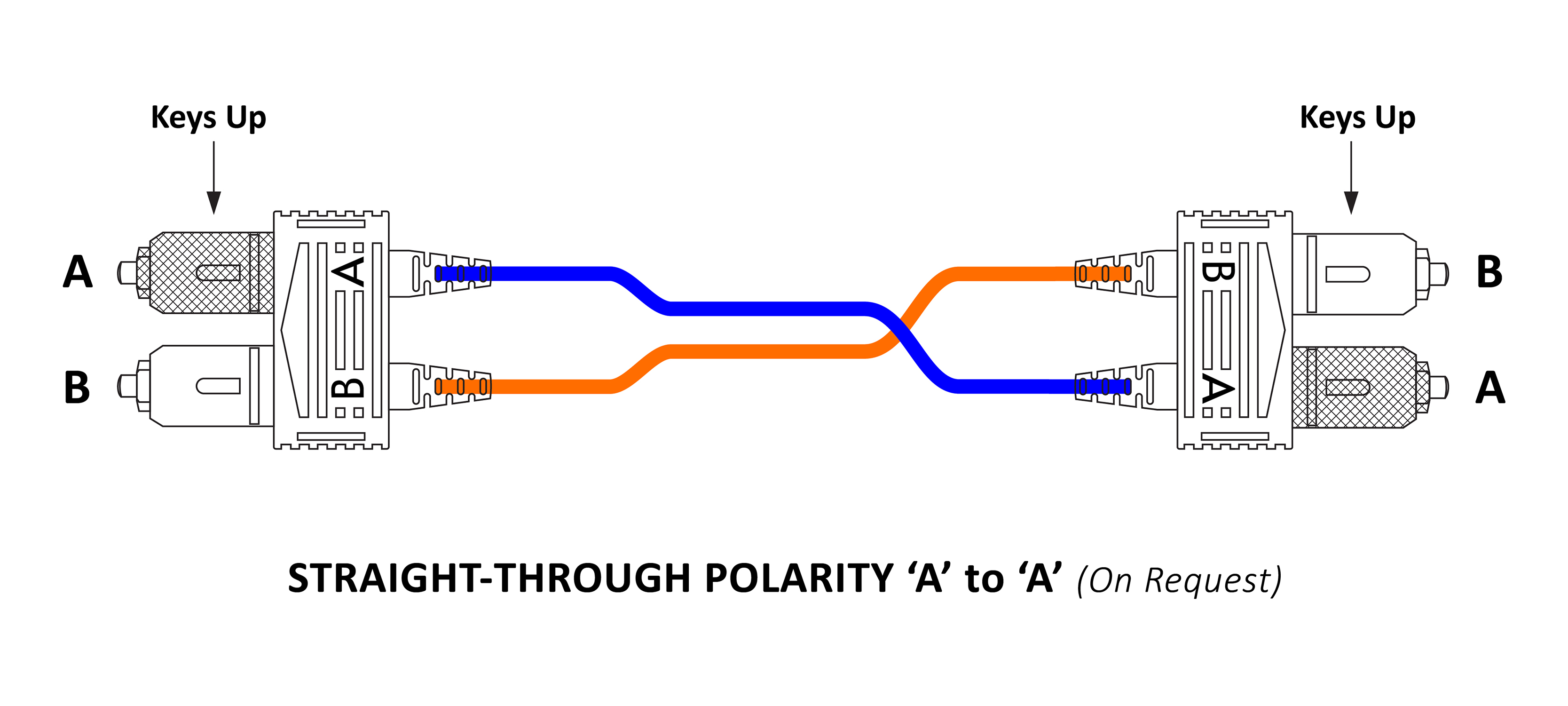
02 A-A (Straight Through) Polarity
A less common configuration, (A-A) polarity has transmit aligning with transmit and receive aligning with receive. Since this does not form a functional connection for most standard applications, A-A polarity typically requires specialized equipment or is used in unique network setups.
Maintaining Polarity with LC and SC Connectors:
In fiber optic networks, maintaining polarity with LC and SC duplex connectors is essential to ensure the transmit (Tx) and receive (Rx) signals are correctly aligned between devices. Improper polarity can disrupt data flow, causing errors and potential network downtime. Here are key methods for maintaining polarity with LC and SC connectors:
1. Use of A-B Duplex Patch Cords
- A-B Polarity: The standard configuration uses A-B duplex patch cords, which align Tx on one end with Rx on the other end, ensuring proper signal flow.
- Color Coding: Many patch cords are color-coded (e.g., blue and white for Tx and Rx) to make identification and installation easier, reducing the chance of misalignment.
2. Keyed Connectors
- Physical Keying: Many LC and SC connectors come with keyed connectors that enforce a one-way connection, helping maintain polarity by only allowing connections in the correct orientation.
- Alignment Pins: Some connectors also include pins to keep Tx and Rx ports in line, ensuring consistent polarity across connections.
3. Orientation Markings
- Labeling and Color Markings: LC and SC connectors often feature labeling or color marks to indicate Tx and Rx ends, simplifying the installation and maintenance process.
- Connector Positioning: Proper orientation of connectors in patch panels and cassettes is also important for polarity. For example, A-B orientation across both ends helps keep Tx and Rx aligned.
Why It’s Important?
Correct LC/SC duplex polarity is vital for maintaining a clear path for data transmission. If polarity is not maintained, the Tx and Rx fibers may not align correctly, leading to communication errors, disrupted data flow, and potentially costly troubleshooting in high-density or high-speed network environments.
Proper polarity practices are foundational in fiber optic networking, ensuring that data flows accurately and efficiently in both enterprise and data center settings.
MTP®/MPO Polarity
MTP®/MPO polarity refers to the correct alignment of transmit (Tx) and receive (Rx) signals in multi-fiber MTP®/MPO connectors, commonly used in high-density fiber optic networks like data centers. These connectors house multiple fibers (such as 8, 12, or 24) in a single connector, allowing for parallel data transmission over multiple channels. Proper polarity is essential to ensure that each fiber carrying a Tx signal connects to a corresponding Rx signal in the paired device.
If you take a quick look, you will find that plenty of data centers are shifting to 40G and 100G transmission. Now, in order to adapt with this change, MTP®/MPO technology is getting introduced to meet the rising demand of high density patching. Remember, a fiber optic link will always need two fibers for proper duplex communications. Make sure the equipment on the link is rightly connected at each end. It is important to note that high density connectivity require more than 2 fibers in a link, which in a way makes it quite complex in order to keep up with the accurate polarity right across a fiber network. This should be carefully noted especially when using the multi-fiber MTP®/MPO components.
Study says that there are technicians who would prefer using pre-terminated MTP®/MPO components specifically designed with polarity protection.
Structure of the MTP®/MPO Connector
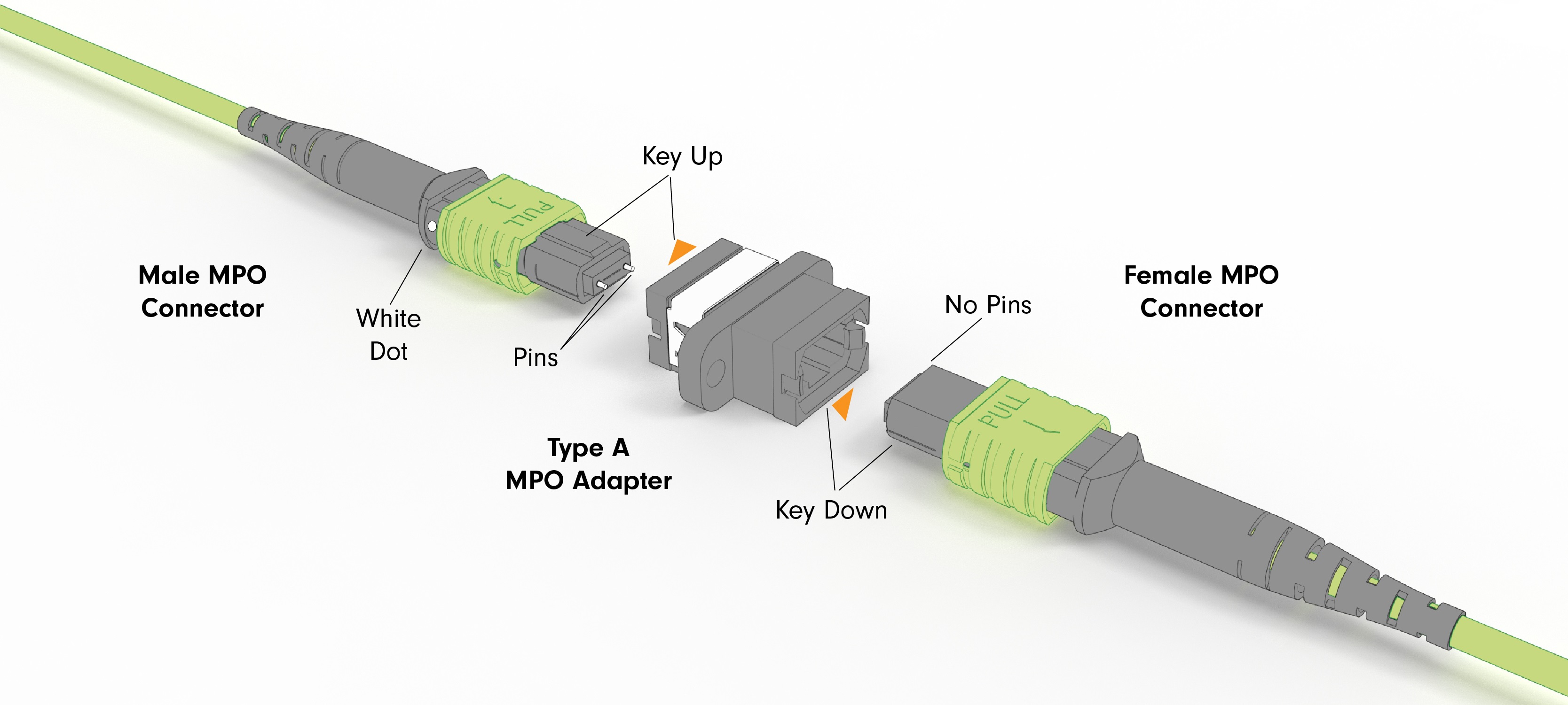
When the discussion is on polarity, the MTP®/MPO connector plays a very important role. This connector has a key placed on one side of the body with two positions in it. The fiber holes in the body of the connector are numbered in order (from left to right). Each of the connectors is marked with a white dot in order to designate the positions when plugged in. You can further divide the MTP®/MPO connectors into female and male connector.
Here’s the basic structure as follows:

In order to ensure proper alignment of the connectors while mating the 2 connectors, the MTP/MPO connectors utilize a socket and a pin feature.
Here’s what it looks:
Polarization Methods (Type-A/B/C)
Three Polarization Methods of MTP®/MPO Trunk Cable Type-A (Straight-Through), Type-B (Reversed) and Type-C (Pair Flipped).
Type-A (Straight-Through): In this polarity configuration, the fibers run straight-through from one end to the other, meaning that transmit (Tx) fibers on one side are aligned with receive (Rx) fibers on the other side. For example, a fiber in position 1 (P1) on one connector will connect directly to position 1 (P1) on the opposite connector. The fiber sequence for a 12-fiber Type A MTP®/MPO cable is as follows:

Type-B (Reversed): In Type B polarity, the positions of the Tx and Rx fibers are reversed at one end of the connection. This means the fiber at position 1 (P1) on one connector aligns with position 12 (P12) on the opposite connector, and so on. The fiber sequence for a 12-fiber Type B cable is shown below:

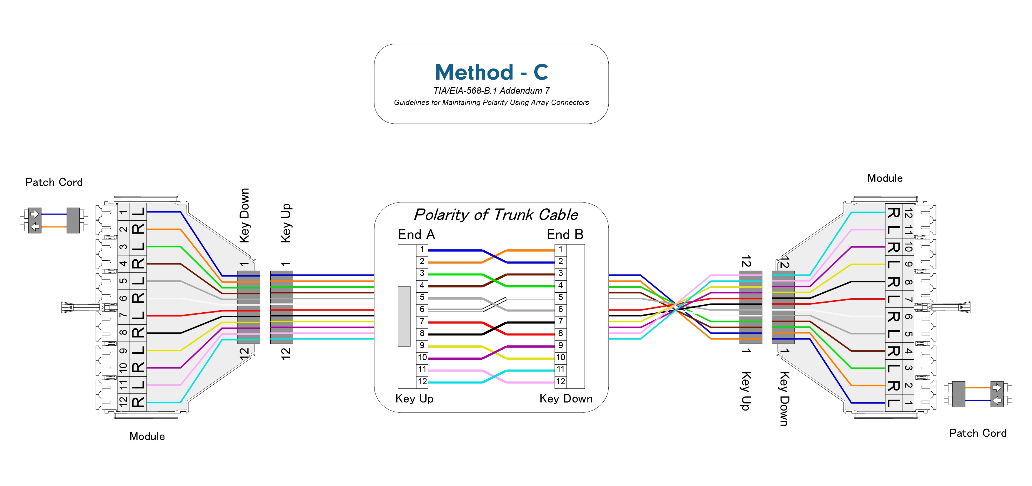
Type-C (Pair-Flipped): In Type C polarity, the positions of individual fiber pairs are flipped rather than reversing the entire set of transmit and receive fibers. This means the fiber in position 1 on one end is shifted to position 2 on the opposite end, and the fiber in position 2 on one end is shifted to position 1 on the other end, continuing this pattern for each fiber pair. The fiber sequence for a 12-fiber Type C MTP®/MPO cable is shown below:

MTP®/MPO Polarity Management Methods
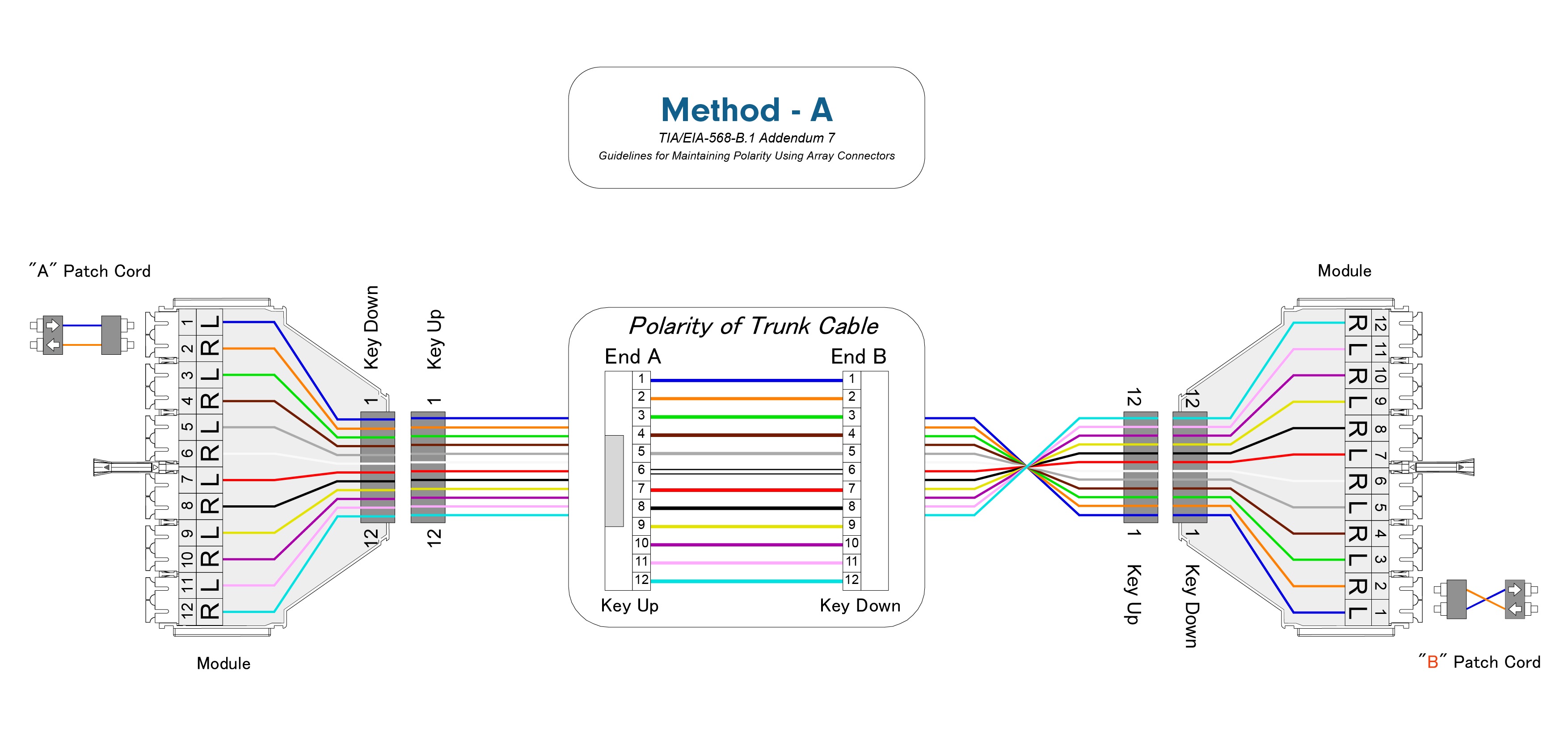
The proper MTP®/MPO polarity methods are defined here in this article by TIA/EIA 568 standard as Method A, Method Bx and Method C. A general optical link requires two optical fibers to complete the entire transmission process. For example, the optical module has a receiving end (Rx) and a transmitting end (Tx). When in use, it is necessary to ensure that the receiving end and the transmitting end are in an interconnected state, and such matching between the transmitting end and the receiving end at both ends of the optical link is known as polarity.
In common cabling systems, connectors such as LC and SC can easily be matched, so there is no polarity issue. However, for pre-terminated, high-density MTP®/MPO cabling systems, polarity issues must be addressed. MPO Trunk cables used here in the figures below are suitable for up to 100G applications to connect between equipment or to interconnect panels and modules in the data center. These MTP®/MPO Trunks are small form factor high density fiber connector assemblies used in high density applications.
Method - A
Polarity Universal Bx
Method - C
| View | Download |