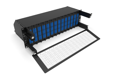
Applications 40G QSFP+ and 100G QSFP28 (Base-8) MPO-MPO Networks
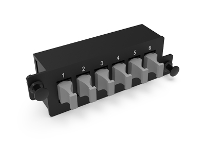
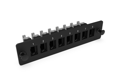
The 40G QSFP+ and 100G QSFP28 (Base-8) MPO-MPO network modules are designed for high-speed data center applications requiring reliable, scalable, and efficient networking. These modules utilize Base-8 MPO (Multi-Fiber Push-On) connectors, which offer streamlined connectivity and easier cable management, critical in high-density environments.
The 40G and 100G MPO-MPO Base-8 solutions deliver a robust platform for seamless, low-latency connectivity across critical network segments, making them a strategic choice for future-proofing data infrastructure.
Key Features:
- 40G QSFP+: Provides up to 40 Gbps over 8 fibers, commonly deployed for shorter-reach, high-speed connections within data centers.
- 100G QSFP28: Offers up to 100 Gbps bandwidth, ideal for applications requiring greater throughput with Base-8 MPO cabling.
- Enhanced Efficiency: Simplifies cable routing, reduces footprint, and cuts power consumption in high-density setups.
- Flexibility: Base-8 MPO systems offer adaptability for future network upgrades, allowing easy transition to higher-speed networks without extensive recabling.
Key Applications:
- Data Centers: Supports the bandwidth needs of cloud and enterprise data centers, enabling smooth data flow for high-performance computing and storage systems.
- Telecommunications: Suitable for telecommunications providers who need to handle heavy traffic loads with minimal latency.
- Campus and Backbone Networks: Enables high-throughput interconnectivity across extensive network infrastructures.
- Virtualization and Cloud Applications: Optimizes for fast data transfers necessary for cloud-based applications and virtualization tasks.
Creating a Three Cable Link
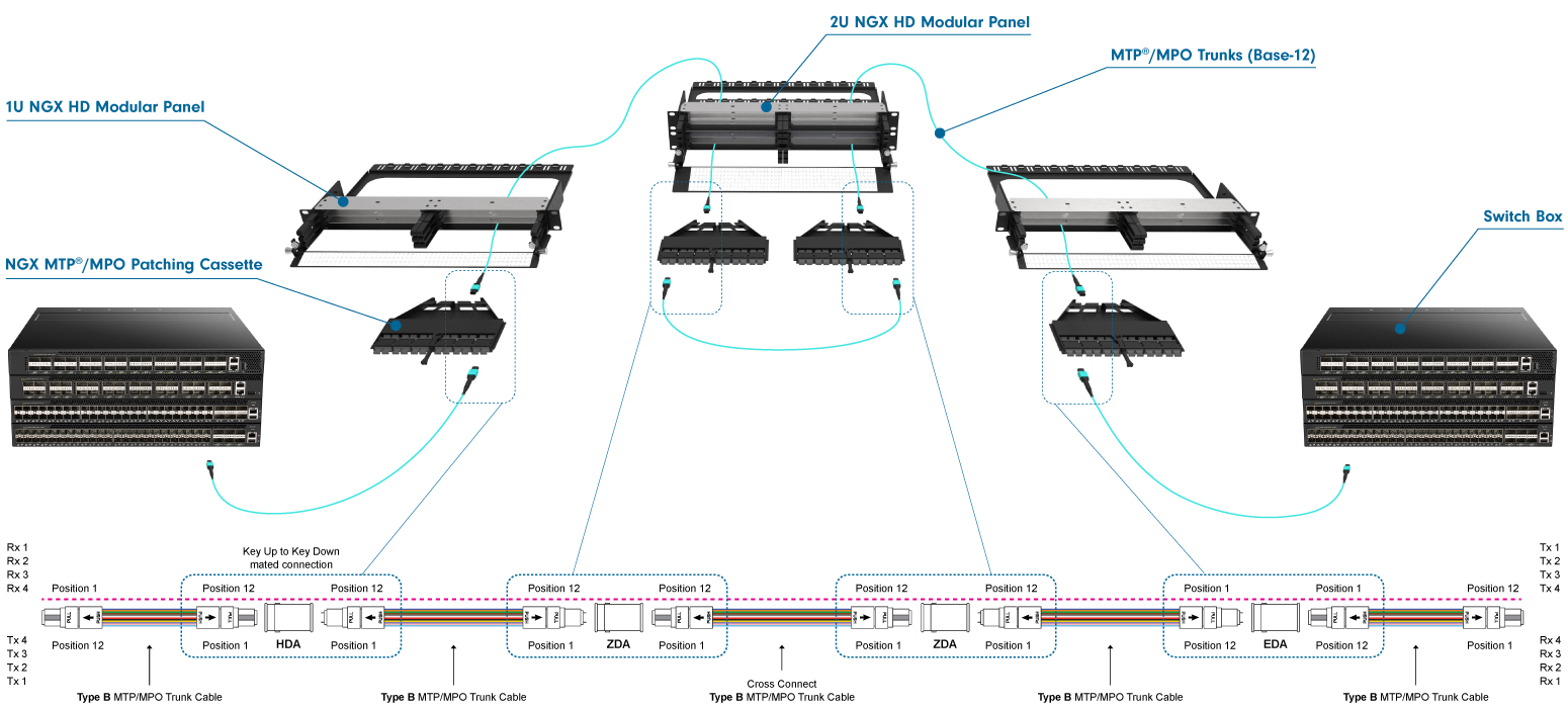
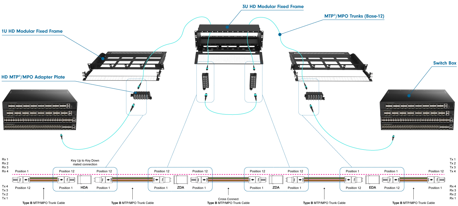
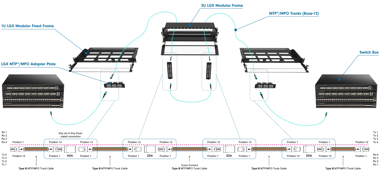
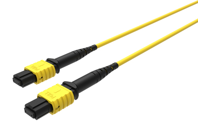
To establish a three-cable link for 40G and 100G networking, the international standard specifies "Method B." This method is distinct from cable polarity, even though it uses cables with polarity B. Method B requires three polarity B cables and two key-up/key-down adapters. The setup includes a trunk cable with male connectors positioned between two racks, while the patch cables on either end are female-to-female.
Note: The trunk cable with male connectors used here differs from the setup for 1G to 25G duplex networking, where trunk cables are female, and MPO-to-LC cassettes have male MPO ports at the rear.
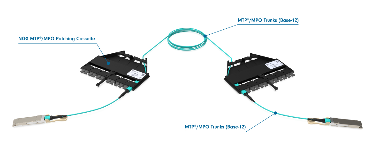
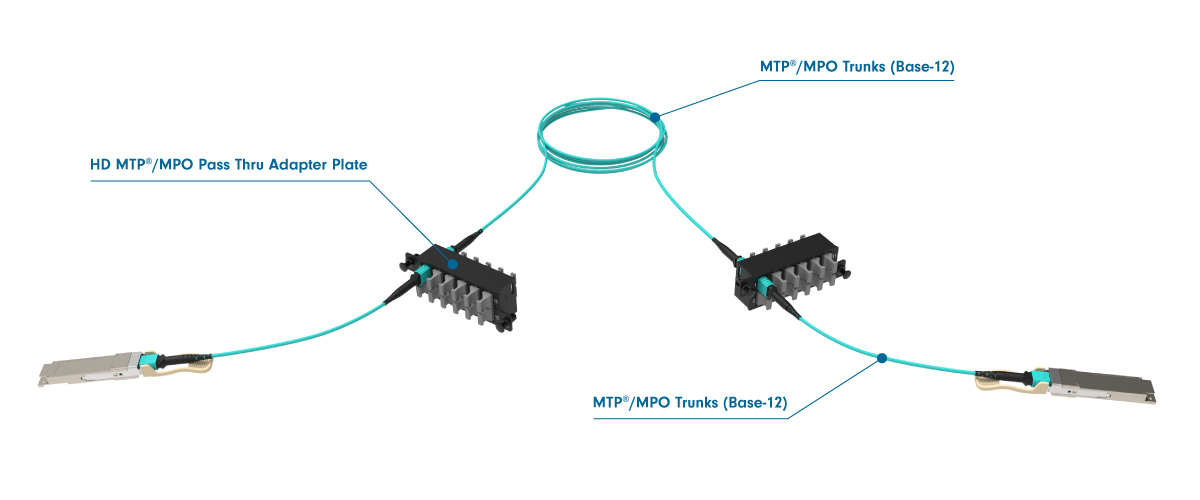
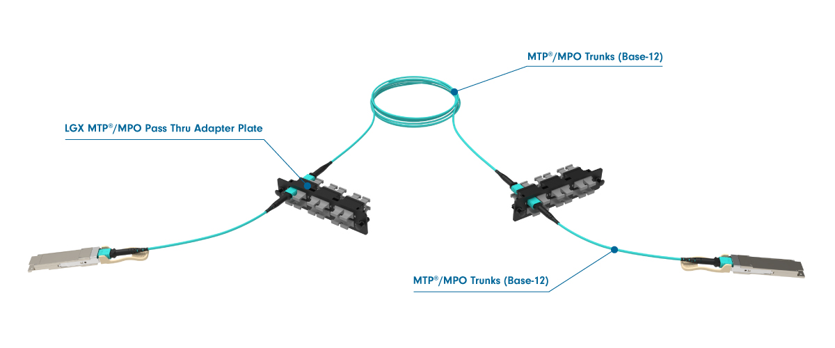
Three Cable Link Diagram:
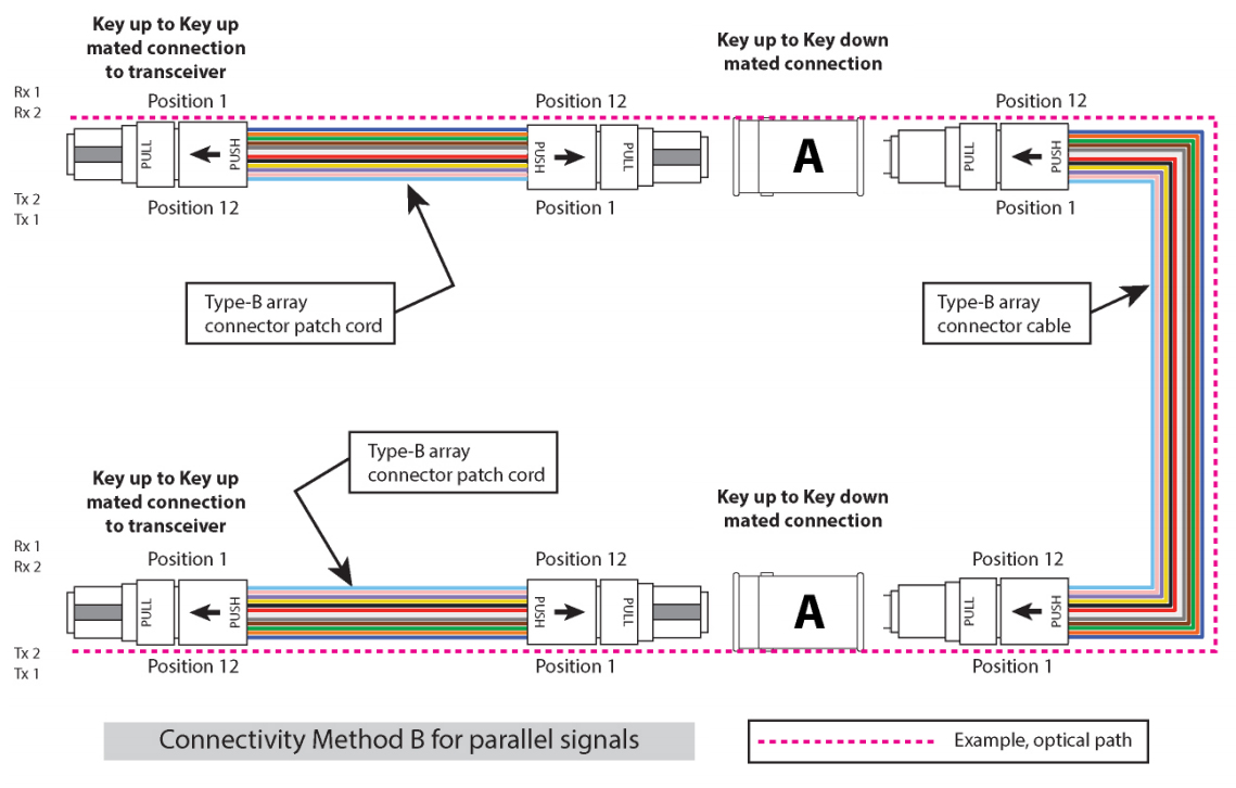
While the three-cable channel is accurately depicted, it can be challenging to trace the signal path through the cables. The representation below provides a clearer illustration of the link.

Creating a Five Cable Link (Cross Connect)
To create a five-cable link connecting ports through a distribution area (cross-connect patch field), the following method is used:
Using an odd number of cables in the channel, combined with key-up/key-down adapters and polarity B cables, will always ensure the correct polarity. Similar to the three-cable link, the trunk cables feature male connectors, while the patch cords and cross-connect cables use female connectors.
